?
Semiconductor Components Industries, LLC, 2008
May, 2008 ?
Rev. 2
1
Publication Order Number:
MBR10H100CT/D
MBR10H100CT
SWITCHMODE
Power Rectifier
100 V, 10 A
Features and Benefits
?
Low Forward Voltage: 0.61 V @ 125°C
?
Low Power Loss/High Efficiency
?
High Surge Capacity
?
175°C Operating Junction Temperature
?
10 A Total (5.0 A Per Diode Leg)
?
Guard?Ring for Stress Protection
?
Pb?Free Package is Available
Applications
?
Power Supply ?
Output Rectification
?
Power Management
?
Instrumentation
Mechanical Characteristics:
?
Case: Epoxy, Molded
?
Epoxy Meets UL 94 V?0 @ 0.125 in
?
Weight: 1.9 Grams (Approximately)
?
Finish: All External Surfaces Corrosion Resistant and Terminal
Leads are Readily Solderable
?
Lead Temperature for Soldering Purposes:
260°C Max. for 10 Seconds
?
Shipped 50 Units Per Plastic Tube
MAXIMUM RATINGS
Please See the Table on the Following Page
*For additional information on our Pb?Free strategy and soldering details, please
download the ON Semiconductor Soldering and Mounting Techniques
Reference Manual, SOLDERRM/D.
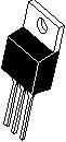
TO?220AB
CASE 221A
PLASTIC
2
3
4
1
SCHOTTKY BARRIER
RECTIFIER
10 AMPERES
100 VOLTS
1
3
2, 4
MARKING
DIAGRAM
AYWW
B10H100G
AKA
A = Assembly Location
Y = Year
WW = Work Week
B10H100 = Device Code
G = Pb?Free Package
AKA = Polarity Designator
http://onsemi.com
Device Package Shipping
ORDERING INFORMATION
MBR10H100CT TO?220 50 Units/Rail
MBR10H100CTG TO?220
(Pb?Free)
50 Units/Rail


发布紧急采购,3分钟左右您将得到回复。
相关PDF资料
MBR10L60CTG
DIODE SCHOTTKY 60V 5A TO220-3
MBR1535CT
DIODE SCHOTTKY 15A 35V TO-220AB
MBR1545CTG
DIODE SCHOTTKY 45V 7.5A TO220AB
MBR1560CT
DIODE SCHOTTKY 15A 60V TO220-3
MBR20100CTP
DIODE SCHOTTKY 20A 100V TO-220
MBR20100CTTU
DIODE SCHOTTKY 100V 10A TO220-3
MBR20150CT-G
DIODE SCHOTTKY 20A 150V TO-220AB
MBR20150CTTU
DIODE SCHOTTKY DL 150V 10A TO220
相关代理商/技术参数
MBR10H100CTHE3/45
功能描述:肖特基二极管与整流器 100 Volt 10A Dual 250 Amp IFSM RoHS:否 制造商:Skyworks Solutions, Inc. 产品:Schottky Diodes 峰值反向电压:2 V 正向连续电流:50 mA 最大浪涌电流: 配置:Crossover Quad 恢复时间: 正向电压下降:370 mV 最大反向漏泄电流: 最大功率耗散:75 mW 工作温度范围:- 65 C to + 150 C 安装风格:SMD/SMT 封装 / 箱体:SOT-143 封装:Reel
MBR10H100-E3/45
功能描述:肖特基二极管与整流器 100 Volt 10A Single 250 Amp IFSM RoHS:否 制造商:Skyworks Solutions, Inc. 产品:Schottky Diodes 峰值反向电压:2 V 正向连续电流:50 mA 最大浪涌电流: 配置:Crossover Quad 恢复时间: 正向电压下降:370 mV 最大反向漏泄电流: 最大功率耗散:75 mW 工作温度范围:- 65 C to + 150 C 安装风格:SMD/SMT 封装 / 箱体:SOT-143 封装:Reel
MBR10H100HE3/45
功能描述:肖特基二极管与整流器 100 Volt 10A Single 250 Amp IFSM RoHS:否 制造商:Skyworks Solutions, Inc. 产品:Schottky Diodes 峰值反向电压:2 V 正向连续电流:50 mA 最大浪涌电流: 配置:Crossover Quad 恢复时间: 正向电压下降:370 mV 最大反向漏泄电流: 最大功率耗散:75 mW 工作温度范围:- 65 C to + 150 C 安装风格:SMD/SMT 封装 / 箱体:SOT-143 封装:Reel
MBR10H150CT
功能描述:肖特基二极管与整流器 10 Amp 150 Volt Dual RoHS:否 制造商:Skyworks Solutions, Inc. 产品:Schottky Diodes 峰值反向电压:2 V 正向连续电流:50 mA 最大浪涌电流: 配置:Crossover Quad 恢复时间: 正向电压下降:370 mV 最大反向漏泄电流: 最大功率耗散:75 mW 工作温度范围:- 65 C to + 150 C 安装风格:SMD/SMT 封装 / 箱体:SOT-143 封装:Reel
MBR10H150CT_07
制造商:VISHAY 制造商全称:Vishay Siliconix 功能描述:Dual Common-Cathode High-Voltage Schottky Rectifier
MBR10H150CT_08
制造商:VISHAY 制造商全称:Vishay Siliconix 功能描述:Dual Common-Cathode High-Voltage Schottky Rectifier
MBR10H150CT-E3/45
功能描述:肖特基二极管与整流器 150 Volt 10A Dual Common-Cathode RoHS:否 制造商:Skyworks Solutions, Inc. 产品:Schottky Diodes 峰值反向电压:2 V 正向连续电流:50 mA 最大浪涌电流: 配置:Crossover Quad 恢复时间: 正向电压下降:370 mV 最大反向漏泄电流: 最大功率耗散:75 mW 工作温度范围:- 65 C to + 150 C 安装风格:SMD/SMT 封装 / 箱体:SOT-143 封装:Reel
MBR10H200CT
功能描述:肖特基二极管与整流器 10 Amp 200 Volt Dual RoHS:否 制造商:Skyworks Solutions, Inc. 产品:Schottky Diodes 峰值反向电压:2 V 正向连续电流:50 mA 最大浪涌电流: 配置:Crossover Quad 恢复时间: 正向电压下降:370 mV 最大反向漏泄电流: 最大功率耗散:75 mW 工作温度范围:- 65 C to + 150 C 安装风格:SMD/SMT 封装 / 箱体:SOT-143 封装:Reel